Omron N-Series Controller Modular Machine Configuration Based on EtherCAT Network Nodes
This document details how to programmatically configure a modular machine based on the connected EtherCAT nodes. The purpose of this task is to have a program common to multiple machine types where the attached hardware is used to define the ultimate functionality. This methodology has trade-offs relative to other modular strategies like derived devices, with advantages such as:
- SD card backup can be used for multiple machine configurations versus requiring Sysmac Studio to download the correct hardware configuration. This allows a third party to program the device without the need for them to purchase Sysmac Studio
- OEM machine builders can sell a module to their customer to enable additional functionality without changing the program
This system also has disadvantages such as:
- Requiring more up front code, planning and system design
- Potentially consuming more EtherCAT nodes than required by actual machines
Configuring the EtherCAT Network
Add All Potential Nodes, Configure Them to Start Disabled
The initial configuration of the project should contain all of the nodes possible in any machine configuration, even if there is no actual machine configuration that uses all the connected nodes. The example below can potentially support 4 different machine configurations. No attached nodes, node 4, connected, node 7 connected, or both connected.


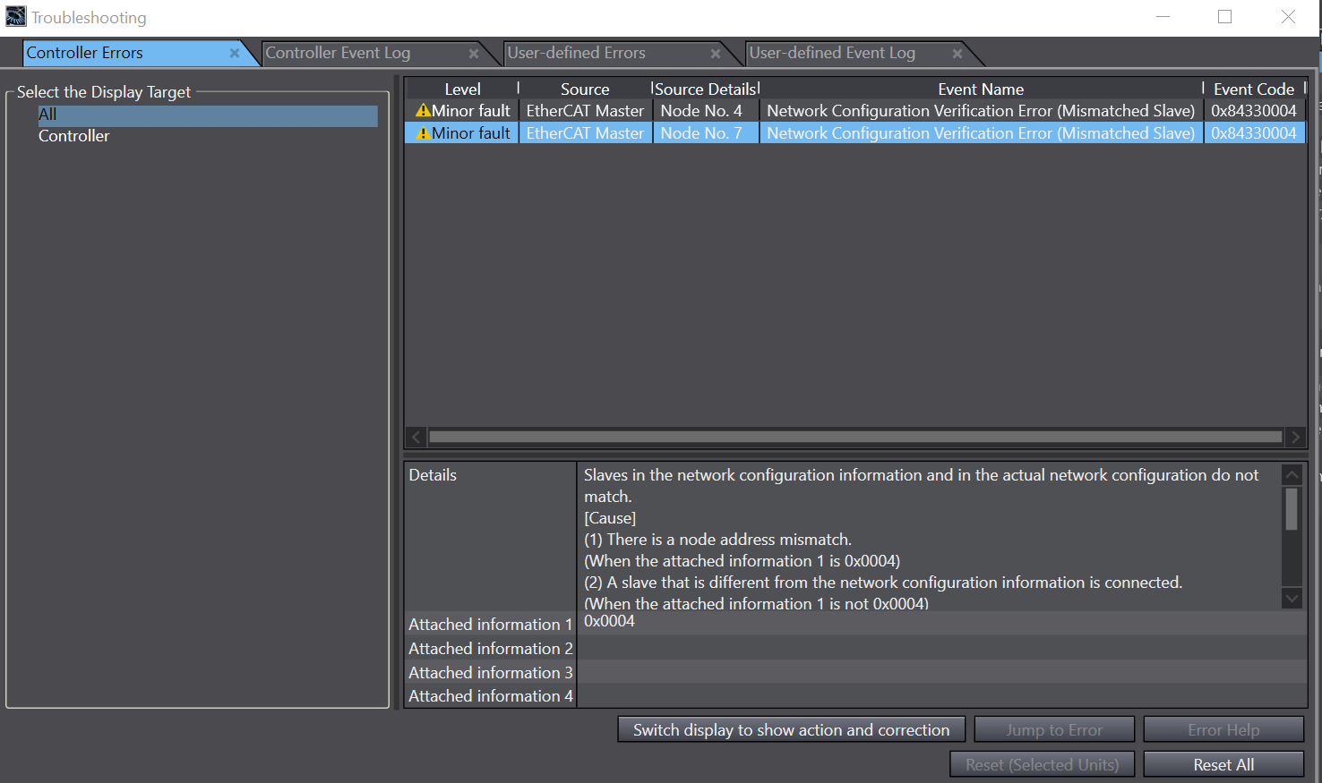
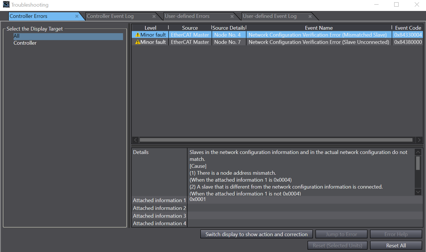
With all of the EtherCAT network nodes configured, the system will be able to detect whether the connected nodes are correct in many cases. The screen capture below shows the verification error that occurs when the node numbers are swapped on the two EtherCAT couplers.
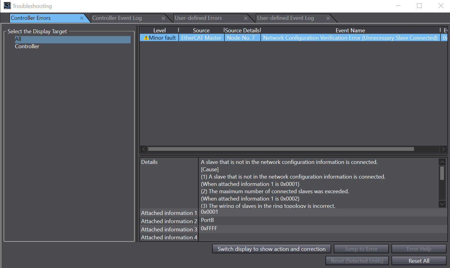
And this screen capture shows the error that is generated with the correct node numbers, but incorrect topology. This error is generated if node 4 is placed after node 7 in the network.
If only node 7 exists, the system will work fine ASSUMING THEY ARE CONFIGURED TO START DISABLED. If this step is missed, the system will try to add them to the network as is and fail with a mix of topology and verification errors.
Determine Machine Type and Enable Nodes
With the EtherCAT network setup to accept all nodes, the program should be structured to perform the following tasks:
- Pause for a short time. This step is to allow all of the nodes to power up. Since the program is determining the machine type by detecting the nodes on the network, it is important that they be given time to startup and establish communication. Proceed with caution on determining the pause time, as the system may function correctly when only the controller is restarted, but fail when the controller and nodes undergo a full power cycle.
- Execute a process where the controller compares the network nodes to an array of node configurations that represent valid machines. This will determine the index of the correct machine if it exists in the MachineConfigurations array, and will set an IllegalMachineConfiguration user fault if the network does not match a valid configuration.
- After the completion of the previous step, if a valid machine configuration is identified, the program will use use the EC_ChangeEnableSetting function block to enable all nodes in the corresponding MachineConfigurations array.
Results
To test the program, the two EtherCAT node system from the “Configuring the EtherCAT Network” section will be used. In this simple system, the programmer could simply implement the type checks with simple ladder logic, but as nodes are added the complexity quickly justifies using an algorithmic approach that is demonstrated in the referenced program.
Demonstration 1: All Machine Configurations are Valid
In this example all 4 possible combinations of machine are considered valid. This is accomplished by populating the 2-dimensional MachineConfigurations array with 4 possible 192 arrays of Boolean. The 192 is to match the size of the _EC_EntrySlavTbl, _EC_PDSlavTbl and _EC_DisableSlavTbl system arrays for the NX102 that are used in the code. Other controllers have larger arrays and can be modified accordingly.
The configuration shows index 1 as a machine with only node 4 connected, index 2 with only node 4 connected and index 3 with both connected and index 4 with none connected.

In this test where the controller is powered on with those 4 topology, the results in order will be:


Where the _EC_PDSlaveTbl entry shows that the node is successfully enabled, and PDO data is being exchanged.
Demonstration 2: Both Nodes on the Same Machine is Invalid
In this example, the case where not all combinations of nodes are valid is demonstrated. This is accomplished by removing the invalid combination from the MachineConfigurations array. This will be a common occurrence as machines start to have many combinations, as some configurations will be incompatible or unsupported. In these cases it is important that the incompatibility is detected and no EtherCAT nodes are enabled.
The array below shows that we have removed the machine where both nodes are present, and left in the other three combinations.

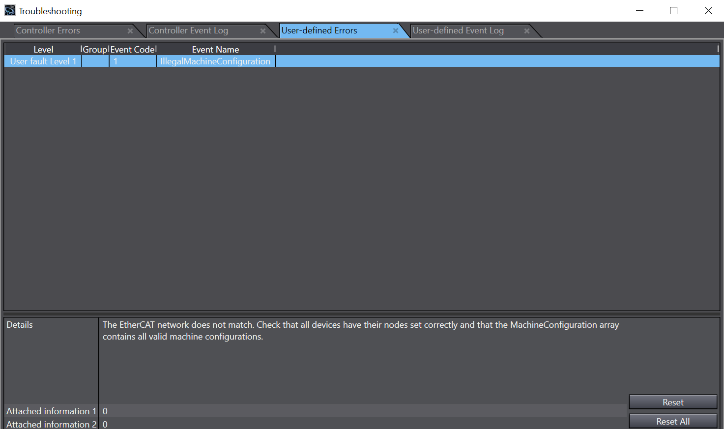
When the device is powered up in this configuration, the Controller Status shows ERR/ALM and the Troubleshooting window’s User Alarms tab shows the following diagnostic info:
